
Page 230 - Robot Builders Source Book - Gordon McComb
P. 230
218 Transporting Devices
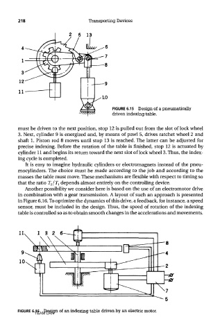
FIGURE 6.15 Design of a pneumatically
driven indexing table.
must be driven to the next position, stop 12 is pulled out from the slot of lock wheel
3. Next, cylinder 9 is energized and, by means of pawl 5, drives ratchet wheel 2 and
shaft 1. Piston rod 8 moves until stop 13 is reached. The latter can be adjusted for
precise indexing. Before the rotation of the table is finished, stop 12 is actuated by
cylinder 11 and begins its return toward the next slot of lock wheel 3. Thus, the index-
ing cycle is completed.
It is easy to imagine hydraulic cylinders or electromagnets instead of the pneu-
mocylinders. The choice must be made according to the job and according to the
masses the table must move. These mechanisms are flexible with respect to timing so
that the ratio r 2/7\ depends almost entirely on the controlling device.
Another possibility we consider here is based on the use of an electromotor drive
in combination with a gear transmission. A layout of such an approach is presented
in Figure 6.16. To optimize the dynamics of this drive, a feedback, for instance, a speed
sensor, must be included in the design. Thus, the speed of rotation of the indexing
table is controlled so as to obtain smooth changes in the accelerations and movements.
FIGURE 6.16 Design of an indexing table driven by an electric motor.
TEAM LRN