
Page 231 - Robot Builders Source Book - Gordon McComb
P. 231
6.3 Rotational Transportation 219
Table 1 is mounted on shaft 2, which also bears gearwheel 3. The latter is engaged with
pinion 4 driven by motor 5. Through control unit 7, tachogenerator 6 creates feedback
to control the speed of motor 5. Another sensor 8 measures the angle of rotation of
indexing table 1 and gives commands to the driving motor 5, through unit 7. To ensure
a precise stopping of the table, a suitable brake must be employed. The further it is
located from the axis of rotation, the higher the accuracy of indexing that can be
achieved. This brake can be designed, for example, as shown in Figure 6.16. Here,
conical brake 9, which is driven by electromagnet 10, provides the needed immobi-
lization of the table when it is inserted into the corresponding conical opening 11. This
electromagnet also is controlled by unit 7. The motor 5 chosen for the indexing table
drive can be a DC or stepping motor and unit 7 must be designed accordingly. The
indexing mechanism considered here belongs to the class of polar manipulators with
one degree of freedom.
Often indexing tables or similar mechanisms carry out two motions, that is, the
movement has two degrees of freedom. The additional degree is usually movement
along the rotating shaft. We have already considered an example of this kind. The layout
of an automatic membrane tin-plating (Figure 2.10) machine includes an indexing
mechanism of this kind. Here the mechanism has suction cups. Alternatively, these
may be electromagnets energized at appropriate times to grip the part being processed,
or mechanical grippers actuated by any means.
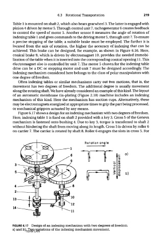
Figure 6.17 shows a design for an indexing mechanism with two degrees of freedom.
Here, indexing table 1 is fixed on shaft 2 provided with a key 3. Cross 5 of the Geneva
mechanism is fastened onto bushing 4. Due to key 3, torque is transferred to shaft 2
without hindering the shaft from moving along its length. Cross 5 is driven by roller 6
on carrier 7. The carrier is rotated by shaft 8. Roller 6 engages the slots in cross 5. For
FIGURE 6.17 Design of an indexing mechanism with two degrees of freedom,
a) and b): Two variations of the indexing mechanism movement.
TEAM LRN