
Page 235 - Robot Builders Source Book - Gordon McComb
P. 235
6.4 Vibrational Transportation 223
smaller; or two, the gap between base 10 and tip 13 of the catch is less than the height
of the roller so that the roller is pulled out from the gripper and remains in this posi-
tion. (When the next roller is caught here it will push this roller out into a collector.)
This mechanism provides unstressed catching and loading of blanks (details, parts)
in appropriate positions. The speed of the gripper at catching and loading moments
is zero. It is also possible to use several arms that work simultaneously. The speed and
acceleration of the moving elements change smoothly, while some of the moving
masses rotate permanently. Thus, the dynamics of this mechanism are much better
than with the Geneva mechanism, for instance. This results in high productivity,
because of the possibility of using much higher speeds than allowed in the other mech-
anisms discussed earlier.
As a disadvantage we must mention the fact that the parts do not absolutely stop
at any point. The gripper centers (and hence the centers of the gripped details) actu-
ally move about 0.1-0.15 mm during the rotation of the driving lever by about 5°-10°
around the "stop" points of positions I, II, HI, IV andV
From the point of view of dynamics, this mechanism is nearly a permanently rotat-
ing device. This reminds us of the continuously acting automatic rotational machines
mentioned in Chapter 1 (see Figure 1.25). It is worthwhile to mention that it is possi-
ble to combine these permanently rotating rotors with the hypocyclic transporting
device. To do so, the speed of the gripper at the top of the hypocycloid (points A in
Figure 6.19) must be equal to that of the rotor.
6.4 Vibrational Transportation
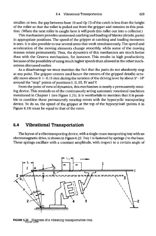
The layout of a vibrotransporting device, with a single-mass transporting tray with an
electromagnetic drive, is shown in Figure 6.22. Tray 1 is fastened by springs 2 to the base.
These springs oscillate with a constant amplitude, with respect to a certain angle of
FIGURE 6.22 Diagram of a vibrating transportation tray.
TEAM LRN