
Page 240 - Robot Builders Source Book - Gordon McComb
P. 240
228 Feeding and Orientation Devices
7.2 Feeding of Liquid and Granular Materials
We begin the discussion with automatic feeding of liquids, which includes, for example:
• Automatic filling of bottles, cans, and other containers with milk, beer, oil, dyes,
lubricants, etc.;
• Automatic distribution of fuel, dye, glue, etc., to definite positions and elements
of an automatic machine;
• Automatic lubrication of machine joints, guides, shafts, etc.
Here, two kinds of feeding exist—continuous and dosewise.
Flowmeters of every kind provide automatic control for continuous feeding of
liquids. Such flowmeters were discussed and illustrated in Chapter 5. They are included
in the control layout and create feedbacks ensuring the desired level of consumption
accuracy. These flowmeters are useful for providing uniformity of dye consumption in
automatic dyeing machines.
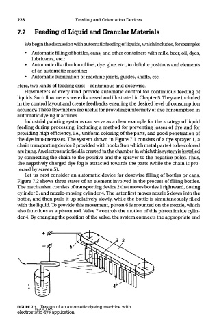
Industrial painting systems can serve as a clear example for the strategy of liquid
feeding during processing, including a method for preventing losses of dye and for
providing high efficiency, i.e., uniform coloring of the parts, and good penetration of
the dye into crevasses. The system shown in Figure 7.1 consists of a dye sprayer 1, a
chain transporting device 2 provided with hooks 3 on which metal parts 4 to be colored
are hung. An electrostatic field is created in the chamber in which this system is installed
by connecting the chain to the positive and the sprayer to the negative poles. Thus,
the negatively charged dye fog is attracted towards the parts (while the chain is pro-
tected by screen 5).
Let us next consider an automatic device for dosewise filling of bottles or cans.
Figure 7.2 shows three states of an element involved in the process of filling bottles.
The mechanism consists of transporting device 2 that moves bottles 1 rightward, dosing
cylinder 3, and nozzle-moving cylinder 4. The latter first moves nozzle 5 down into the
bottle, and then pulls it up relatively slowly, while the bottle is simultaneously filled
with the liquid. To provide this movement, piston 6 is mounted on the nozzle, which
also functions as a piston rod. Valve 7 controls the motion of this piston inside cylin-
der 4. By changing the position of the valve, the system connects the appropriate end
FIGURE 7.1 Design of an automatic dyeing machine with
TEAM LRN
electrostatic dye application.