
Page 243 - Robot Builders Source Book - Gordon McComb
P. 243
7.3 Feeding of Strips, Rods, Wires, Ribbons, Etc. 231
shaft 2 which is driven by motor 3 via transmission 4 (here a belt transmission is shown).
The screw is located inside tubular housing 5, which has inlet and outlet sleeves 6 and
7, respectively. The material is poured into sleeve 6 and due to rotation of the screw,
is led to sleeve 7 where it exits for subsequent use or distribution. Obviously, the speed
of the screw's rotation defines the rate of consumption of the material.
7.3 Feeding of Strips, Rods, Wires, Ribbons, Etc.
Linear materials are often used in manufacturing. Their advantage is that they are
intrinsically oriented. (We will discuss orientation problems later.) Thus, the feeding
operation requires relatively simple manipulations. Indeed, in unwinding wire from
the coil it is supplied on, only one point on this wire needs to be determined to com-
pletely define its position. Thus, an effective technical solution for feeding this kind of
material is two rollers gripping the wire (strip, rod, etc.), from two sides and pulling or
pushing it by means of the frictional forces developed between them and the mater-
ial. We have already used this approach in examples considered in Chapter 2 (for
example, Figures 2.2 and 2.4). Continuous rotation of the rollers provides, of course,
continuous feeding of the material, which is effective for continuous manufacturing
processes. However, for a periodical manufacturing process, feeding must be inter-
rupted. One way to do this is based on the use of a separate drive controlled by the
main controller of the machine. Such an example was discussed in Chapter 2. When
the feeding time is a small fraction of the whole period, this solution is preferable.
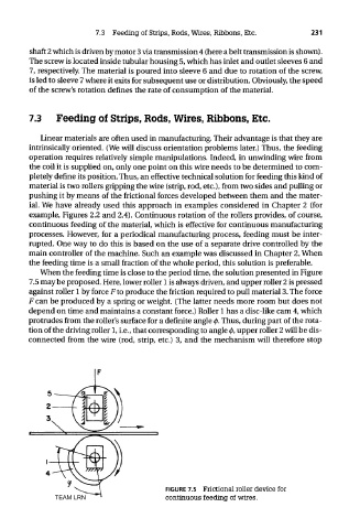
When the feeding time is close to the period time, the solution presented in Figure
7.5 may be proposed. Here, lower roller 1 is always driven, and upper roller 2 is pressed
against roller 1 by force Fto produce the friction required to pull material 3. The force
F can be produced by a spring or weight. (The latter needs more room but does not
depend on time and maintains a constant force.) Roller 1 has a disc-like cam 4, which
protrudes from the roller's surface for a definite angle 0. Thus, during part of the rota-
tion of the driving roller 1, i.e., that corresponding to angle 0, upper roller 2 will be dis-
connected from the wire (rod, strip, etc.) 3, and the mechanism will therefore stop
FIGURE 7.5 Frictional roller device for
TEAM LRN continuous feeding of wires.