
Page 246 - Robot Builders Source Book - Gordon McComb
P. 246
234 Feeding and Orientation Devices
Obviously, when
self-locking occurs, and no N c force (no spring) is needed to lock the strip, wire. etc.
The devices in Figures 7.6 and 7.7 must be designed so that they do not reach the
self-locking state, to ensure easy release of the material when the direction of the
applied force is changed. Thus, the relations usually should be
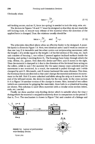
The principles described above allow an effective feeder to be designed. A possi-
ble layout is shown in Figure 7.8. Here, two identical units I and II work in concert so
that one (say, I) is immobile and the other carries out reciprocating movement, with
the length L of a stroke equal to the length L of the fed section of the strip, etc. Each
unit consists of housing 1, two rollers 2 pressed against inclined surfaces inside the
housing, and spring 3 exerting force N c. The housings have holes through which the
strip, ribbon, etc., passes. How does this device act? First, unit II moves to the right.
Then the material is clamped in it due to the direction of the frictional force acting on
the rollers, while in unit I the material (for the same reason) stays unlocked and its
movement is not restricted. As a result, the material is pulled through unit I while
clamped by unit II. Afterwards, unit II moves backward the same distance. This time,
the frictional forces are directed so that unit I clamps the material and resists its move-
ment to the left. Unit II is now unlocked and slides along the strip as it moves. At the
end of the leftward stroke, the device is ready for the next cycle. In the cross section
A-A in Figure 7.8 another version of the clamps is shown. Here, instead of two rollers
(which are convenient for gripping flat materials), three balls in a cylindrical housing
are shown. This solution is used when materials with a circular cross section (wires,
rods, etc.) are fed.
Finally, we show another strip-feeding device which is suitable when the time r
during which the material is stopped is relatively short in comparison to the period T;
that is, T»T. The mechanism is shown in Figure 7.9a) and consists of a linkage and
TEAM LRN