
Page 249 - Robot Builders Source Book - Gordon McComb
P. 249
7.4 Feeding of Oriented Parts from Magazines 237
Figure 7.1 Ib) shows how this can be done for a contact bar of an electromagnetic relay.
Platinum-iridium contacts are riveted in the two small openings in the split end of the
bar (see cross section in Figure 7.lie)). This riveting is much more convenient to do
while the bars are together in a band-like structure, as in the illustration. Strip 1 is
introduced into the stamp. It has a certain width b and is guided into the tool by sup-
ports 2. At line A the openings (blackened in the illustration) are cut. In the next step
the split end of the bar is shaped and next the lower end is completed. Thus, section
LJ is needed to produce the bar. From line B the band-like semiproduct is ready.
However, the bars are kept connected by two cross-pieces 3 and 4. The contact is riveted
in section L,, either on the same or another machine. An example of this process is
explained in Chapter 8. Obviously, in either case no special efforts are needed to bring
the bar oriented to the riveting position. When the contact is in its place the bars must
be separated. This happens at line C by means of two punches which cut the remain-
ing cross-pieces (blackened spots in the illustration).
The above examples (Figures 7.10 and 7.11) are typical high-productivity automatic
processes, where automatic feeding of parts must be as rapid as possible. Therefore,
the contrivances described above are justified. However, often the processing time is
relatively long and the automatic operation does not suffer much if feeding is simpli-
fied. This brings us to the idea of hoppers or magazines. The classical means of automat-
ing industrial processes use a wide range of different kinds of hoppers, some of which
are discussed below.
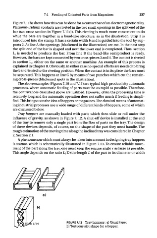
Tray hoppers are manually loaded with parts which then slide or roll under the
influence of gravity, as shown in Figure 7. 12. A shut-off device is installed at the end
of the tray to remove only a single part from the flow of parts on the tray. The design
of these devices depends, of course, on the shape of the part they must handle. The
rough estimation of the moving time along the inclined tray was considered in Chapter
2, Section 2.1.
A phenomenon which must always be taken into account in designing tray hoppers
is seizure, which is schematically illustrated in Figure 7.13. To ensure reliable move-
ment of the part along the tray, one must keep the seizure angle j as large as possible.
This angle depends on the ratio L/D (the length L of the part to its diameter or width
TEAM LRN FIGURE 7.12 Tray hoppers: a) Usual type;
b) Tortuous slot shape for a hopper.