
Page 250 - Robot Builders Source Book - Gordon McComb
P. 250
238 Feeding and Orientation Devices
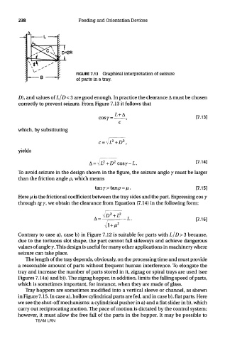
FIGURE 7.13 Graphical interpretation of seizure
of parts in a tray.
D), and values of L/D < 3 are good enough. In practice the clearance A must be chosen
correctly to prevent seizure. From Figure 7.13 it follows that
which, by substituting
yields
To avoid seizure in the design shown in the figure, the seizure angle 7 must be larger
than the friction angle p, which means
Here ju is the factional coefficient between the tray sides and the part. Expressing cos 7
through tgy, we obtain the clearance from Equation (7.14) in the following form:
Contrary to case a), case b) in Figure 7.12 is suitable for parts with L/D>3 because,
due to the tortuous slot shape, the part cannot fall sideways and achieve dangerous
values of angle 7. This design is useful for many other applications in machinery where
seizure can take place.
The length of the tray depends, obviously, on the processing time and must provide
a reasonable amount of parts without frequent human interference. To elongate the
tray and increase the number of parts stored in it, zigzag or spiral trays are used (see
Figures 7.14a) and b)). The zigzag hopper, in addition, limits the falling speed of parts,
which is sometimes important, for instance, when they are made of glass.
Tray hoppers are sometimes modified into a vertical sleeve or channel, as shown
in Figure 7.15. In case a), hollow cylindrical parts are fed, and in case b), flat parts. Here
we see the shut-off mechanisms: a cylindrical pusher in a) and a flat slider in b), which
carry out reciprocating motion. The pace of motion is dictated by the control system;
however, it must allow the free fall of the parts in the hopper. It may be possible to
TEAM LRN