
Page 255 - Robot Builders Source Book - Gordon McComb
P. 255
7.5 Feeding of Parts from Bins 243
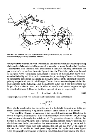
FIGURE 7.20 Pocket hopper: a) Pockets for elongated details; b) Pockets for
short details; c) Radially oriented pockets.
their preferred orientation so as to minimize the resistance forces appearing during
their motion. When l/d»l this preferred orientation is along the chord of the disc.
The larger the ratio, the more parts are oriented in that way. Naturally, in this case the
pockets should be made as shown in Figure 7.20a). For l/d=2 the pockets are formed
as in Figure 7.20b). To increase the number of pockets on the disc, they may be ori-
ented radially (Figure 7.20c)), which increases the productivity of the device. However,
to compel the parts to fall into radial pockets, the surface of the disc must be appro-
priately shaped with special radial bulges. The maximum rotational speed of the disc
is determined by the falling speed of the parts into outlet tray 3. For this purpose the
length of the pocket in case a) and its width in cases b) and c) must be great enough
to provide clearance A. Thus, for the three types a), b), and c), respectively,
The peripheral speed V of the disc can be estimated from the formula
Here, g is the acceleration due to gravity, and h is the height the part must fall to get
free of the disc (obviously, h equals the thickness of the part or d, its diameter).
The next kind of feeder we consider is the so-called sector hopper. This device is
shown in Figure 7.21 and consists of an oscillating sector 1 provided with slot 2, housing
3, outlet tray 4, and usually shut-off element 5. The parts 6 are thrown in bulk into the
bowl of the housing. When the sector turns so that the slot is in its lower position, the
slot is immersed in the parts and catches a certain number of them by chance as it is
lifted by the sector. These then slide out along the slot and into tray 4. The shape of
the slot must be suitable for the shape of the parts handled by the device (see Figure
7.22). To permit free movement of blanks in the slot and optimum feeding and orien-
TEAM LRN