
Page 259 - Robot Builders Source Book - Gordon McComb
P. 259
7.5 Feeding of Parts from Bins 247
vibrated by electromagnet 7 fastened in the middle of base 4. The electromagnet is
made of core 8 and coil 9. To prevent transfer of vibrations to the system or machine
on which the feeder is mounted, the latter can be installed on three springs 10, of rel-
atively low stiffness. Pin 11 restrains the feeder from moving too much. When coil 9 of
magnet 7 is energized by alternating current (usually the standard frequency of 50 Hz
is used), an alternating force pulls armature 12. This force causes spiral oscillation of
the bowl (because of inclined springs 3). Under certain conditions the alternating accel-
eration of this movement causes the parts in the groove to proceed, as we showed
earlier for a vibrating tray (Figure 6.22).
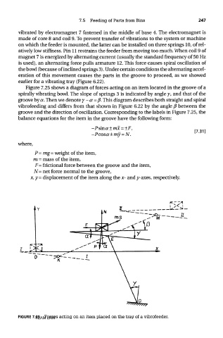
Figure 7.25 shows a diagram of forces acting on an item located in the groove of a
spirally vibrating bowl. The slope of springs 3 is indicated by angle 7, and that of the
groove by a. Then we denote y-a=/3. This diagram describes both straight and spiral
vibrofeeding and differs from that shown in Figure 6.22 by the angle ft between the
groove and the direction of oscillation. Corresponding to the labels in Figure 7.25, the
balance equations for the item in the groove have the following form:
where,
P = mg=weight of the item,
m = mass of the item,
F= frictional force between the groove and the item,
N= net force normal to the groove,
x, y - displacement of the item along the x- and y-axes, respectively.
FIGURE 7.25 Forces acting on an item placed on the tray of a vibrofeeder.
TEAM LRN