
Page 264 - Robot Builders Source Book - Gordon McComb
P. 264
252 Feeding and Orientation Devices
• Motion is due to inertia; therefore, there is less risk of damage to the parts.
• Constant and uniform speed of the parts is convenient for orientation (see next
section).
• These devices are relatively simple, having no rotating links, and seizure of parts
is less possible.
• The feeding speed can be easily tuned and controlled.
The vibrofeeder can be oscillated by an electromagnet (as mentioned above), pneu-
modrive, or mechanical means. Usually driving is done by a force field (electromag-
netic or inertial); only the mechanical drive can function kinematically, thus ensuring
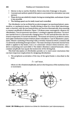
a constant amplitude of vibration. Figure 7.26 shows some nonmagnetic vibrators for
vibrofeeders. Case a) represents two masses 1 rotating in opposite directions. The resul-
tant inertial force is a harmonically changing force Fin the vertical direction (the hor-
izontal components Hcancel one another). The masses are driven by an electric motor,
and a gear mechanism ensures rotation phase coincidence. Case b) illustrates a pneu-
matic vibrator consisting of housing I with a toroidal channel in which a massive ball
2 is driven by air flowing through nozzle 3. The mass develops a harmonic inertial force
which is applied to the feeder. Case c) is a kinematic vibrator where eccentric cam 1
drives connecting rod 2 and slider 3. The slider's vibration is almost harmonic, with a
constant amplitude that equals the eccentricity of the driving link.
This brief description of vibrofeeders permits us to reach some conclusions that
can have important implications for designing vibrofeeders:
1. The peripheral acceleration of the tray of the spiral feeder is described in the
form
where a is the vibration amplitude, and CD is the frequency of the excitation force
or movement.
TEAM LRN
FIGURE 7.26 Nonmagnetic vibrators as drives for vibrofeeders (and vibroconveyors).