
Page 269 - Robot Builders Source Book - Gordon McComb
P. 269
7.6 General Discussion of Orientation of Parts 257
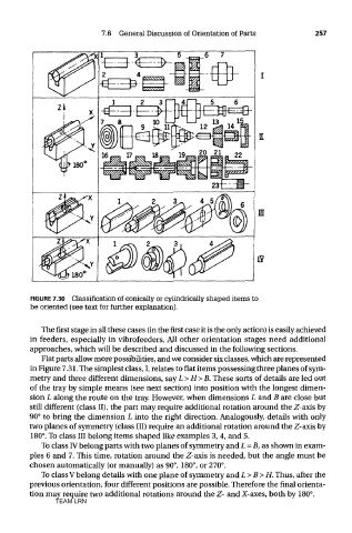
FIGURE 7.30 Classification of conically or cylindrically shaped items to
be oriented (see text for further explanation).
The first stage in all these cases (in the first case it is the only action) is easily achieved
in feeders, especially in vibrofeeders. All other orientation stages need additional
approaches, which will be described and discussed in the following sections.
Flat parts allow more possibilities, and we consider six classes, which are represented
in Figure 7.31. The simplest class, I, relates to flat items possessing three planes of sym-
metry and three different dimensions, say L>H>B. These sorts of details are led out
of the tray by simple means (see next section) into position with the longest dimen-
sion L along the route on the tray. However, when dimensions L and B are close but
still different (class II), the part may require additional rotation around the Z axis by
90° to bring the dimension L into the right direction. Analogously, details with only
two planes of symmetry (class III) require an additional rotation around the Z-axis by
180°. To class III belong items shaped like examples 3, 4, and 5.
To class IV belong parts with two planes of symmetry and L = B, as shown in exam-
ples 6 and 7. This time, rotation around the Z-axis is needed, but the angle must be
chosen automatically (or manually) as 90°, 180°, or 270°.
To class V belong details with one plane of symmetry and L>B>H. Thus, after the
previous orientation, four different positions are possible. Therefore the final orienta-
tion may require two additional rotations around the Z- and X-axes, both by 180°.
TEAM LRN