
Page 272 - Robot Builders Source Book - Gordon McComb
P. 272
260 Feeding and Orientation Devices
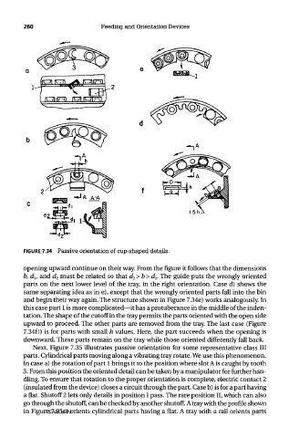
FIGURE 7.34 Passive orientation of cup-shaped details.
opening upward continue on their way. From the figure it follows that the dimensions
b, d lt and d 2 must be related so that d 2>b>d l. The guide puts the wrongly oriented
parts on the next lower level of the tray, in the right orientation. Case d) shows the
same separating idea as in e), except that the wrongly oriented parts fall into the bin
and begin their way again. The structure shown in Figure 7.34e) works analogously. In
this case part 1 is more complicated—it has a protuberance in the middle of the inden-
tation. The shape of the cutoff in the tray permits the parts oriented with the open side
upward to proceed. The other parts are removed from the tray. The last case (Figure
7.34f)) is for parts with small h values. Here, the part succeeds when the opening is
downward. These parts remain on the tray while those oriented differently fall back.
Next, Figure 7.35 illustrates passive orientation for some representative class III
parts. Cylindrical parts moving along a vibrating tray rotate. We use this phenomenon.
In case a) the rotation of part 1 brings it to the position where slot A is caught by tooth
3. From this position the oriented detail can be taken by a manipulator for further han-
dling. To ensure that rotation to the proper orientation is complete, electric contact 2
(insulated from the device) closes a circuit through the part. Case b) is for a part having
a flat. Shutoff 2 lets only details in position I pass. The rare position II, which can also
go through the shutoff, can be checked by another shutoff. A tray with the profile shown
TEAM LRN
in Figure 7.35c) orients cylindrical parts having a flat. A tray with a rail orients parts