
Page 271 - Robot Builders Source Book - Gordon McComb
P. 271
7.7 Passive Orientation 259
7.7 Passive Orientation
Passive orientation is based on the idea of keeping on the tray only those parts or
details that are oriented as desired. The wrongly oriented parts are simply thrown off
the tray for additional trials. The working principles of this orientation are explained
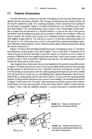
on the basis of examples. Figure 7.32 shows the behavior of a cylindrical part of the
first class (Figure 7.30), running along a chute (Figure 7.32a). If the length L of the cylin-
der is longer than its diameter d, a shutoff element 1 is put in the way of the part in
the feeder, thus throwing every part not in position 2 off the tray. In Figure 7.32b) the
device ensures the output only of parts in a standing position (especially when L is
only slightly longer than d). The tray has a cutout 3, so that the remaining width b of
the tray is b < d/2. Above the tray a catch 1 is located. Thus, parts proceeding in posi-
tion 2 fall when they reach the cutout; otherwise they safely continue the journey along
the tray in orientation 4.
Figure 7.33 shows the handling of cylindrical parts belonging to class 11. The parts
have diameters much greater than their heights. Case a) uses hook 1 shaped so as to
catch the part by its head and take it over the cutout to continue on tray 3. Parts in
position 2 fall back into the supply bin for the next trial. Case b) uses cutout 1 with an
inclined surface. Parts in position 2 fall back into the bin. The dimensions of the part
dictate the dimensions of the cutout.
Cup-shaped items of the same class can be handled by the passive means illustrated
in Figure 7.34. Parts shaped as in case a) have two possible stable positions (the opening
facing upward or downward) on tray 1. Shutoff 2 prevents stacking up of parts. The
curved opening 3 causes parts with the opening facing downward to turn over and fall
onto the lower level of the tray (we are dealing with a spiral vibrofeeder, whose tray is
shaped like a rising spiral) and the part has a chance to land with the opening facing
upward. In this position the parts cross cutout 3 successfully. The modification shown
in Figure 7.34b) throws the "wrongly" oriented parts into the bin of parts at the bottom
of the feeder. For more massive parts of the same class (thicker walls), a cutout (shown
in Figure 7.34c)), with the addition of guide 1, ensures that parts 2 oriented with the
FIGURE 7.32 Passive orientation of
symmetrical cylindrical details.
FIGURE 7.33 Passive orientation of
symmetrical cylindrical details with
TEAM LRN one axis of symmetry.