
Page 241 - Robot Builders Source Book - Gordon McComb
P. 241
7.2 Feeding of Liquid and Granular Materials 229
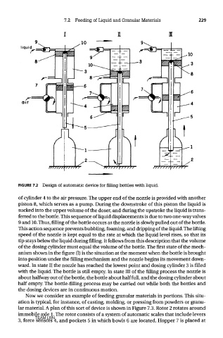
FIGURE 7.2 Design of automatic device for filling bottles with liquid.
of cylinder 4 to the air pressure. The upper end of the nozzle is provided with another
piston 8, which serves as a pump. During the downstroke of this piston the liquid is
sucked into the upper volume of the doser, and during the upstroke the liquid is trans-
ferred to the bottle. This sequence of liquid displacements is due to two one-way valves
9 and 10. Thus, filling of the bottle occurs as the nozzle is slowly pulled out of the bottle.
This action sequence prevents bubbling, foaming, and dripping of the liquid. The lifting
speed of the nozzle is kept equal to the rate at which the liquid level rises, so that its
tip stays below the liquid during filling. It follows from this description that the volume
of the dosing cylinder must equal the volume of the bottle. The first state of the mech-
anism shown in the figure (I) is the situation at the moment when the bottle is brought
into position under the filling mechanism and the nozzle begins its movement down-
ward. In state II the nozzle has reached the lowest point and dosing cylinder 3 is filled
with the liquid. The bottle is still empty. In state III of the filling process the nozzle is
about halfway out of the bottle, the bottle about half full, and the dosing cylinder about
half empty. The bottle-filling process may be carried out while both the bottles and
the dosing devices are in continuous motion.
Now we consider an example of feeding granular materials in portions. This situ-
ation is typical, for instance, of casting, molding, or pressing from powders or granu-
lar material. A plan of this sort of device is shown in Figure 7.3. Rotor 2 rotates around
immobile axle 1. The rotor consists of a system of automatic scales that include levers
TEAM LRN
3, force sensors 4, and pockets 5 in which bowls 6 are located. Hopper 7 is placed at