
Page 234 - Robot Builders Source Book - Gordon McComb
P. 234
222 Transporting Devices
This mechanism must be equivalent to that shown in Figure 6. 19, which means that
rotation angle 0 5 of lever 5 and rotation angle 0 4 of wheel 4 (or the rotation angle of
arm 1) are related by some definite ratio. It is easy to understand that, between any
two positions, 0 5 = 144° = (2/5)360°. With regard to angle 0 4, attention must be paid to
the fact that the length of arc III-IV (as well as those of arcs I-II, II-III, and IV-V; dashed
lines in Figure 6.19) equals the circumference of wheel 4. From this fact it follows that
angle 0 4 may be expressed as
The consequence of this statement is
Thus, Expression (6.8) can be rewritten as
The other condition we must provide is the radius R. This is made by choosing the
proper dimensions for planet gear 7.
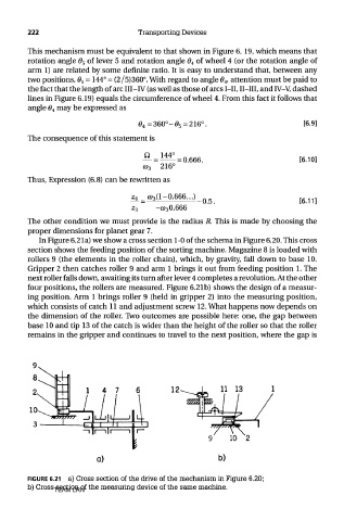
In Figure 6.21a) we show a cross section 1-0 of the schema in Figure 6.20. This cross
section shows the feeding position of the sorting machine. Magazine 8 is loaded with
rollers 9 (the elements in the roller chain), which, by gravity, fall down to base 10.
Gripper 2 then catches roller 9 and arm 1 brings it out from feeding position 1. The
next roller falls down, awaiting its turn after lever 4 completes a revolution. At the other
four positions, the rollers are measured. Figure 6.21b) shows the design of a measur-
ing position. Arm 1 brings roller 9 (held in gripper 2) into the measuring position,
which consists of catch 11 and adjustment screw 12. What happens now depends on
the dimension of the roller. Two outcomes are possible here: one, the gap between
base 10 and tip 13 of the catch is wider than the height of the roller so that the roller
remains in the gripper and continues to travel to the next position, where the gap is
FIGURE 6.21 a) Cross section of the drive of the mechanism in Figure 6.20;
b) Cross section of the measuring device of the same machine.
TEAM LRN