
Page 62 - Robot Builders Source Book - Gordon McComb
P. 62
2.3 How to Determine the Productivity of a Manufacturing Process 51
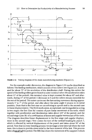
FIGURE 2.14 Timing diagram of the chain manufacturing machine (Figure 2.1).
For the example under discussion, the diagram in Figure 2.14 can be described as
follows: The feeding mechanism, which consists of two rollers (see Figure 2.2), is actu-
ated for about 75° of the revolution of the distribution shaft. During this action the
speed of the feeding rollers grows from 0 to some nominal value (the acceleration takes
about 15° of the period); this nominal value is kept constant for about 45° and after-
wards, during 15° of the period, it decreases to 0 and the rollers remain immobile for
the rest of the period. The cutter carries out the fast cutting movement during approx-
imately 5° to 7° of the period, and after about the same angle it returns to its initial
position. (Note that in the first case we are referring to speeds and in the second case
to linear displacements.) The third mechanism, as explained, can be regarded as acting
in two stages: the first (line 3a) consists of pure linear movement of the tools, which
together with acceleration and deceleration takes about 120° of the period, and the
second stage (Line 3b) of a combination of linear and angular movements of the tools.
(The diagram describes linear displacement in the first stage and angular displace-
ment in the second stage.) Now comes the turn of the vertical bending by punch 7,
which is effected by vertical displacement of the punch and takes about 50° of the
period. Note that in every bending process we envisage a time interval where the tool
rests; this is done to provide stress relief in the bent material of the link. This process
takes about 10° of the period. The fifth line shows the movement of the support 4 which
TEAM LRN