
Page 66 - Robot Builders Source Book - Gordon McComb
P. 66
2.4 The Kinematic Layout 55
run in series one after the other (this is the usual way to think about a manufacturing
process). Figure 2.16b) illustrates the simultaneous running of the operations to econ-
omize the production time. The example shown in Figure 2.10 conforms to this
approach.
Exercises
Show the timing diagrams for the following automatic processes:
1. Four-stroke internal combustion engine. Use the circular approach.
2. Washing machine (any washing regime). Use the diagram given in Figure 2.15.
3. Sewing machine. Use the linear approach.
4. Spring-producing machine (Figure 2.4) for the spring shown in Figure 2.3c).
5. Automatic record player.
2.4 The Kinematic Layout
After the processing layout and timing diagram are finished comes the turn of the
kinematic layout. At this stage the designer has to choose the means by which to effect
the required movements of tools as defined in the processing layout. A variety of
mechanical concepts are at the designer's disposal for this purpose. These may be
known and established concepts; on the other hand, sometimes new concepts must
be found. Any mechanism chosen for carrying out a specific movement needs a drive.
We will now consider and compare those most commonly used, beginning with
mechanical drives. (See Table 2.1.)
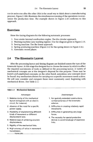
TABLE 2.1 Mechanical Systems
Advantages Disadvantages
1. Relative clarity of the mechanical 1. For spatially extended constructions,
layout (compared with an electric cumbersomeness of the kinematic
circuit, for instance). solution.
2. Absence of the need for a specific 2. Difficulties in creating relatively rapid
power supply. movements.
3. Possibility of implementing different 3. Difficulties in generating very large
kinds of movement or different forces.
displacement laws. 4 The necessity for special protective
4. Relative ease of achieving accurate devices to avoid breakage of expensive
displacements. links.
5. Rigidity of the mechanical links.
6. High accuracy of ratios in movement
transmission.
TEAM LRN