
Page 69 - Robot Builders Source Book - Gordon McComb
P. 69
58 Concepts and Layouts
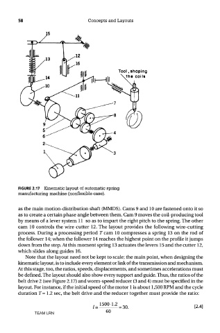
FIGURE 2.17 Kinematic layout of automatic spring
manufacturing machine (nonflexible case).
as the main motion-distribution shaft (MMDS). Cams 9 and 10 are fastened onto it so
as to create a certain phase angle between them. Cam 9 moves the coil-producing tool
by means of a lever system 11 so as to impart the right pitch to the spring. The other
cam 10 controls the wire cutter 12. The layout provides the following wire-cutting
process. During a processing period T cam 10 compresses a spring 13 on the rod of
the follower 14; when the follower 14 reaches the highest point on the profile it jumps
down from the step. At this moment spring 13 actuates the levers 15 and the cutter 12,
which slides along guides 16.
Note that the layout need not be kept to scale; the main point, when designing the
kinematic layout, is to include every element or link of the transmission and mechanism.
At this stage, too, the ratios, speeds, displacements, and sometimes accelerations must
be defined. The layout should also show every support and guide. Thus, the ratios of the
belt drive 2 (see Figure 2.17) and worm-speed reducer (3 and 4) must be specified in the
layout. For instance, if the initial speed of the motor 1 is about 1,500 RPM and the cycle
duration T=\2 sec, the belt drive and the reducer together must provide the ratio:
TEAM LRN