
Page 73 - Robot Builders Source Book - Gordon McComb
P. 73
62 Concepts and Layouts
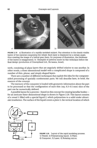
FIGURE 2.19 a) Illustration of a rapidly modeled subject. Pay attention to the clearly visible
layers of the material comprising the wheel. Each layer is displaced by a certain angle,
thus creating the image of a helical gear (here, for purposes of illustration, the thickness
of the layers is exaggerated), b) Examples of patterns made by this technique before the
final design (production of Conceptland Ltd., Ra'anana, Israel).
teeth, consisting of plane layers that are angularly shifted relative to one another. In
other words, a three-dimensional model with a complicated shape is composed of a
number of thin, planar, and simply shaped layers.
There are a number of different techniques that exploit this idea for the computer-
aided processing of spatially cumbersome parts. We will describe here, in brief, the
essence of the concept.
The memory of the computer is loaded with geometric information about the part
to be processed so that the configuration of each thin (say, 0.3-0.5 mm) slice of the
part can be numerically defined.
A possible layout for a process—based on this concept for creating lamellar bodies—
for an intricate three-dimensional shape is shown in Figure 2.20. This layout consists
of a vessel 1 filled with a special liquid 2, which polymerizes to a solid under ultravi-
olet irradiation. The surface of the liquid covers a plate 3, the vertical location of which
FIGURE 2.20 Layout of the rapid modeling process.
1) Vessel; 2) Polymerizing liquid; 3) Plate;
TEAM LRN 4) Computer; 5) Laser; 6) Rotating mirror.