
Page 72 - Robot Builders Source Book - Gordon McComb
P. 72
2.5 Rapid Prototyping 61
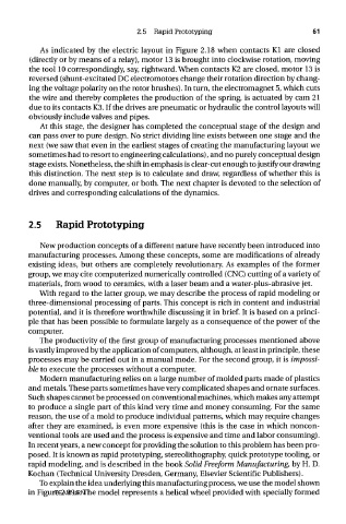
As indicated by the electric layout in Figure 2.18 when contacts Kl are closed
(directly or by means of a relay), motor 13 is brought into clockwise rotation, moving
the tool 10 correspondingly, say, rightward. When contacts K2 are closed, motor 13 is
reversed (shunt-excitated DC electromotors change their rotation direction by chang-
ing the voltage polarity on the rotor brushes). In turn, the electromagnet 5, which cuts
the wire and thereby completes the production of the spring, is actuated by cam 21
due to its contacts K3. If the drives are pneumatic or hydraulic the control layouts will
obviously include valves and pipes.
At this stage, the designer has completed the conceptual stage of the design and
can pass over to pure design. No strict dividing line exists between one stage and the
next (we saw that even in the earliest stages of creating the manufacturing layout we
sometimes had to resort to engineering calculations), and no purely conceptual design
stage exists. Nonetheless, the shift in emphasis is clear-cut enough to justify our drawing
this distinction. The next step is to calculate and draw, regardless of whether this is
done manually, by computer, or both. The next chapter is devoted to the selection of
drives and corresponding calculations of the dynamics.
2.5 Rapid Prototyping
New production concepts of a different nature have recently been introduced into
manufacturing processes. Among these concepts, some are modifications of already
existing ideas, but others are completely revolutionary. As examples of the former
group, we may cite computerized numerically controlled (CNC) cutting of a variety of
materials, from wood to ceramics, with a laser beam and a water-plus-abrasive jet.
With regard to the latter group, we may describe the process of rapid modeling or
three-dimensional processing of parts. This concept is rich in content and industrial
potential, and it is therefore worthwhile discussing it in brief. It is based on a princi-
ple that has been possible to formulate largely as a consequence of the power of the
computer.
The productivity of the first group of manufacturing processes mentioned above
is vastly improved by the application of computers, although, at least in principle, these
processes may be carried out in a manual mode. For the second group, it is impossi-
ble to execute the processes without a computer.
Modern manufacturing relies on a large number of molded parts made of plastics
and metals. These parts sometimes have very complicated shapes and ornate surfaces.
Such shapes cannot be processed on conventional machines, which makes any attempt
to produce a single part of this kind very time and money consuming. For the same
reason, the use of a mold to produce individual patterns, which may require changes
after they are examined, is even more expensive (this is the case in which noncon-
ventional tools are used and the process is expensive and time and labor consuming).
In recent years, a new concept for providing the solution to this problem has been pro-
posed. It is known as rapid prototyping, stereolithography, quick prototype tooling, or
rapid modeling, and is described in the book Solid Freeform Manufacturing, by H. D.
Kochan (Technical University Dresden, Germany, Elsevier Scientific Publishers).
To explain the idea underlying this manufacturing process, we use the model shown
in Figure 2.19a. The model represents a helical wheel provided with specially formed
TEAM LRN