
Page 201 - Robotics Designing the Mechanisms for Automated Machinery
P. 201
5.2 Speed and Flow-Rate Sensors 189
minimal speeds to avoid dynamic effects such as vibration and overshoot. In addition,
some special speed-control situations may also require speed sensors.
The simplest way (conceptually, not technically) to solve the problem of speed mea-
surement is to obtain the derivative of the displacement of appropriate elements versus
time. It is easy to imagine that a variable voltage obtained from the output of a dis-
placement-measuring bridge could be differentiated by means of some microproces-
sor or even some more simple device. For a digital displacement system, speed
estimation Vrequires a timer and a pulse counter. The timer turns the counter on and
stops it at the end of a certain time interval At. Thus, the counter indicates the number
of pulses n per time interval.
For example, the device shown in Figure 5.10 can be and is used also for speed mea-
surement, especially when a digital readout is desired.
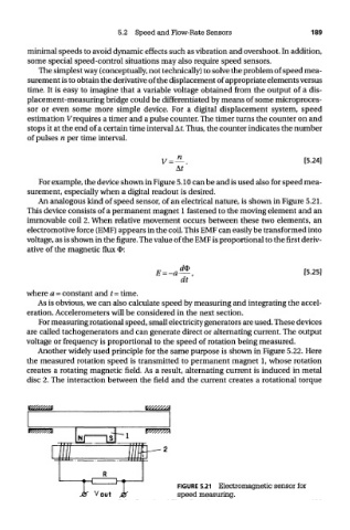
An analogous kind of speed sensor, of an electrical nature, is shown in Figure 5.21.
This device consists of a permanent magnet 1 fastened to the moving element and an
immovable coil 2. When relative movement occurs between these two elements, an
electromotive force (EMF) appears in the coil. This EMF can easily be transformed into
voltage, as is shown in the figure. The value of the EMF is proportional to the first deriv-
ative of the magnetic flux O:
where a = constant and t = time.
As is obvious, we can also calculate speed by measuring and integrating the accel-
eration. Accelerometers will be considered in the next section.
For measuring rotational speed, small electricity generators are used. These devices
are called tachogenerators and can generate direct or alternating current. The output
voltage or frequency is proportional to the speed of rotation being measured.
Another widely used principle for the same purpose is shown in Figure 5.22. Here
the measured rotation speed is transmitted to permanent magnet 1, whose rotation
creates a rotating magnetic field. As a result, alternating current is induced in metal
disc 2. The interaction between the field and the current creates a rotational torque
FIGURE 5.21 Electromagnetic sensor for
speed measuring.