
Page 203 - Robotics Designing the Mechanisms for Automated Machinery
P. 203
5.2 Speed and Flow-Rate Sensors 191
impeller (with small losses) is proportional to the specific kinetic energy Wof the flow,
which is described by the following expression:
where p = density of the liquid and V= speed of the liquid.
The liquid's speed multiplied by the cross-sectional area of the pipe gives the flow
rate or consumption. The accuracy of these devices is about 1-0.3%.
It is conceivably possible to use the well-known Venturi or Pitot tubes for the same
(flow-rate measuring) purpose. However, these sensors require differential pressure
pick-ups which, for low flow rates, may be too coarse. This follows from Expression
3
(5.26). (Note that the dimensions of the specific energy Nm/m and pressure drop
2
N/m are equal.) The chain of information transfer in the turbine-type device is shorter
than in Pitot or Venturi devices. Therefore, in the latter, sensitivity and accuracy get
lost to some extent on the way.
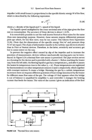
To prevent the negative effect caused by slip of the impeller and to increase the
precision of measurement, devices without mechanically moving parts can be intro-
duced. In Figure 5.24 a thermal flow-rate sensor is presented. The pipe section serves
as a housing for the device and is provided with a heater 1. Before reaching the heater
(say, from the left side), the flowing liquid or gas has a temperature t Q, and after it passes
the heater its temperature rises to the value (t 0 + At). These temperatures are registered
by thermoresistors (or other temperature sensors) 2 and 3, respectively, which together
with constant resistors R create a bridge. Warming the gas by a certain temperature
increment (here At) requires different quantities of heat energy introduced by the heater
for different mass flow rates of the gas. The voltage AV that appears when the bridge
is out of balance is amplified by amplifier 4, and controller 5 changes the heating
current that feeds the heater. The value of the current /gives an indication of the flow
FIGURE 5.24 Thermal flow-rate sensor.