
Page 232 - Robotics Designing the Mechanisms for Automated Machinery
P. 232
220 Transporting Devices
holding the cross during its rest, the curved parts of the cross are locked by disc 9. Shaft
8 also drives cam 10 which is used for raising and lowering the indexing table with the
aid of fork-like follower 11, which is connected to roller 12. Fork 11 is engaged with
bushing 13. The indexing table is balanced by spring 14. This structure allows the double
motion of the indexing mechanism to be carried out. This mechanism can be used,
for example, to take parts (by means of suction cups or other grippers) from their posi-
tions, transfer them to the next positions, and lower them into their places. The move-
ment of the suction cups is graphed in Figure 6.17a).
The indexing mechanism can also be designed so as to carry out recurrent angular
motion in combination with reciprocating vertical motion. A diagram of this motion
is shown in Figure 6.17b). The advantage of this kind of motion is that flexible means
of communication can be used, e.g., electric wires, hoses, pipes, whereas in the pre-
vious case special methods are required to connect suction cups to a central vacuum
pump to avoid leakage of air into the system and prevent the hoses from twisting.
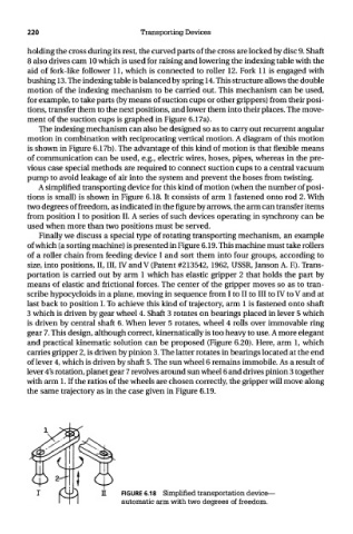
A simplified transporting device for this kind of motion (when the number of posi-
tions is small) is shown in Figure 6.18. It consists of arm 1 fastened onto rod 2. With
two degrees of freedom, as indicated in the figure by arrows, the arm can transfer items
from position I to position II. A series of such devices operating in synchrony can be
used when more than two positions must be served.
Finally we discuss a special type of rotating transporting mechanism, an example
of which (a sorting machine) is presented in Figure 6.19. This machine must take rollers
of a roller chain from feeding device I and sort them into four groups, according to
size, into positions, II, III, IV and V (Patent #213542, 1962, USSR, Janson A. F). Trans-
portation is carried out by arm 1 which has elastic gripper 2 that holds the part by
means of elastic and frictional forces. The center of the gripper moves so as to tran-
scribe hypocycloids in a plane, moving in sequence from I to II to III to IV to V and at
last back to position I. To achieve this kind of trajectory, arm 1 is fastened onto shaft
3 which is driven by gear wheel 4. Shaft 3 rotates on bearings placed in lever 5 which
is driven by central shaft 6. When lever 5 rotates, wheel 4 rolls over immovable ring
gear 7. This design, although correct, kinematically is too heavy to use. A more elegant
and practical kinematic solution can be proposed (Figure 6.20). Here, arm 1, which
carries gripper 2, is driven by pinion 3. The latter rotates in bearings located at the end
of lever 4, which is driven by shaft 5. The sun wheel 6 remains immobile. As a result of
lever 4's rotation, planet gear 7 revolves around sun wheel 6 and drives pinion 3 together
with arm 1. If the ratios of the wheels are chosen correctly, the gripper will move along
the same trajectory as in the case given in Figure 6.19.
FIGURE 6.18 Simplified transportation device—
automatic arm with two degrees of freedom.