
Page 228 - Robotics Designing the Mechanisms for Automated Machinery
P. 228
216 Transporting Devices
We use this opportunity to illustrate another one-revolution mechanism (the pre-
vious one was presented in Figure 4.21). This mechanism is shown in its resting state
in Figure 6.12a). Worm gear 4 (in Figure 6.11 the same numeration) and worm 5 engaged
with it are not moving. In addition, holder 15 locks worm gear 4 by engaging with slot
14 in its hub. Pulley 9 always rotates freely on shaft 6. The pulley has pin 16 which is
disconnected in this situation from the other pin 17 of bushing 18. The command to
begin the movement acts to pull out holder 15 from slot 14 of the worm gear hub. This
also pulls fork 19, which is engaged with bushing 18, rightward and brings the pins 16
and 17 into engagement. Thus, pulley 9 begins to drive bushing 18 and, through a key,
it drives shaft 6 and worm 5 (here we show only one worm transmission). Worm wheel
4 begins to rotate, carrying around with it the levers (in Figure 6.11, levers 3). Now
holder 15 may be freed and spring 20 will press it against the hub, although it cannot
disengage pulley 9 from bushing 18. Only when slot 14 reaches its initial position (the
revolution is finished) does the holder fall into the slot and disconnect pins 16 and 17.
The system is thus returned to the state shown in Figure 6.12a).
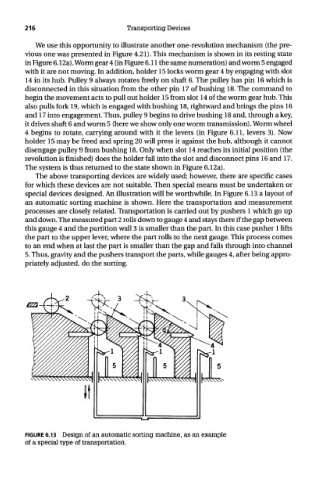
The above transporting devices are widely used; however, there are specific cases
for which these devices are not suitable. Then special means must be undertaken or
special devices designed. An illustration will be worthwhile. In Figure 6.13 a layout of
an automatic sorting machine is shown. Here the transportation and measurement
processes are closely related. Transportation is carried out by pushers 1 which go up
and down. The measured part 2 rolls down to gauge 4 and stays there if the gap between
this gauge 4 and the partition wall 3 is smaller than the part. In this case pusher 1 lifts
the part to the upper lever, where the part rolls to the next gauge. This process comes
to an end when at last the part is smaller than the gap and falls through into channel
5. Thus, gravity and the pushers transport the parts, while gauges 4, after being appro-
priately adjusted, do the sorting.
FIGURE 6.13 Design of an automatic sorting machine, as an example
of a special type of transportation.