
Page 229 - Robotics Designing the Mechanisms for Automated Machinery
P. 229
6.3 Rotational Transportation 217
6.3 Rotational Transportation
Rotational transportation devices are often also called indexing tables. In this section
we consider the drives used most often to achieve interrupted rotation, where, as
before, 7^ is the resting time and T 2 is the time the transporting device moves.
One mechanism—the Geneva drive—has already been discussed (Figures 4.1, 4.4,
4.8). In addition we can mention that combining these drives with gear transmissions
allows variation of the difference between the number of slots in the mechanism and
the number of positions on the indexing table. For instance, a four-slotted Geneva
mechanism transmitting the rotation of the driven link through a gear transmission
having a 1:2 ratio would drive an eight-position indexing table. (The ratio T 2JTi stays
the same as for a four-slotted Geneva mechanism.) To get around the rigid depen-
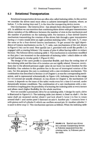
dence of Geneva mechanisms on the T 2/T l ratio, cam mechanisms of the sort shown
in Figure 6.14a) can be used. Here spatial cam 1, provided with scroll-like profile 2, is
engaged with a rotating follower 3 by means of pins 4 (often having rollers to reduce
friction). The follower drives indexing table 5. This mechanism is sometimes modified
so that pins 2 are mounted on the underside of indexing table 1 which slides or rolls
on ball bearings in circular guide 3 (Figure 6.14b)).
The design of the cam's profile is somewhat flexible, and thus the resting time of
the indexing table and the time of its rotation are not rigidly related. However, restric-
tions due to the allowed pressure angle value do not leave too much freedom for this
flexibility. One solution to this problem lies in the use of interrupted rotation of the
cam. For this purpose the cam is combined with a one-revolution mechanism. This
combination was described in Section 4.4 of Chapter 4, as was the corresponding mech-
anism, and is represented schematically in Figure 4.49. Indexing times in the range
0.2-0.5 second are usually obtained. As was shown in Chapter 4, the mechanism (of
course, it depends on the mass of the table) works even for a time 0.4 second, under
dynamically intense conditions. The combination of a cam mechanism with a one-
revolution coupling gives the possibility of actuating the indexing table at every instant
and allows much higher flexibility for the whole machine.
Now we consider a pneumatic drive for an indexing table. A design for such a drive
is illustrated in Figure 6.15. The indexing table (not shown) is fixed on shaft 1. On the
same shaft are mounted ratchet wheel 2 and lock wheel 3. Lever 4 is free to rotate
around shaft 1 and carries pawl 5 fastened on axis 6. Another pin 7 connects lever 4
with piston rod 8 of cylinder 9, which can oscillate around pin 10. Another cylinder 11
is used to drive stop 12. This mechanism operates as follows. When the indexing table
FIGURE 6.14 Spatial cam drives
for a circular transporting device:
a) Follower separated from the
rotating table; b) Follower part of
the table.