
Page 226 - Robotics Designing the Mechanisms for Automated Machinery
P. 226
214 Transporting Devices
the blanks. Now clamps 4 go down to hold the blanks. At this moment, processing
(drilling, assembly, cutting, etc.) may begin and lasts for time interval T. Sometime
during this interval the system must be returned to its initial state. The pawls must be
lifted (cylinder 10) and moved rightward (cylinder 13) where they are lowered (again,
cylinder 10). This completes the cycle of the transporting device, whose duration cycle
equals T.
We may make the following note here. The transportation device discussed above
consists of two manipulators working in concert. One has one degree of freedom
(clamping mechanisms); the second has two degrees of freedom. Of course, both of
them can be controlled by systems of different levels of flexibility. The controls can be
stiff (carried out by a cam mechanism tuned once forever), a computerized system of
steppers allowing flexible programming, or any other level in between.
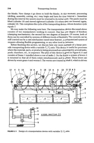
Before finishing this section, we discuss here one more example of a linear peri-
odic transporting device with a variable TjT 2 ratio. This device is useful for processes
where the material, parts, or products being processed are submerged in several tanks,
pools, chambers, etc., in sequence. The plan of this device is given in Figure 6.11 and
consists of frame 1 installed above a row of tanks 2. On the frame a system of levers 3
is mounted so that all of them rotate simultaneously and in phase. These levers are
driven by worm gears 4 and worms 5. The worms are rotated by shaft 6, which is driven
cross section 1-1
FIGURE 6.11 Design of a transportation device with variable ly T 2 ratio.