
Page 225 - Robotics Designing the Mechanisms for Automated Machinery
P. 225
6.2 Linear Transportation 213
FIGURE 6.9 Design of a chainless transportation device with one degree of freedom.
cross-piece and the shaft is made so as to allow rotation of the shaft. During opera-
tion, this mechanism goes through the following sequence of motions. First, pawls 9
must be brought into the down-right position (next to the blanks on their right side),
and clamps 4 are down to hold the blanks. The events are shown also in the timing
diagram (Figure G.lOa). (The description begins at t= 2.) Transportation begins with
lifting clamps (cylinder 6); afterwards cylinder 13 begins its motion leftward, moving
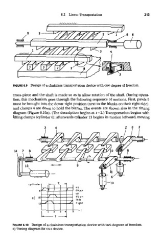
FIGURE 6.10 Design of a chainless transportation device with two degrees of freedom,
a) Timing diagram for this device.