
Page 224 - Robotics Designing the Mechanisms for Automated Machinery
P. 224
212 Transporting Devices
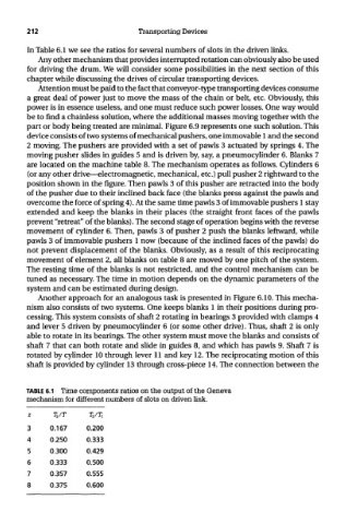
In Table 6.1 we see the ratios for several numbers of slots in the driven links.
Any other mechanism that provides interrupted rotation can obviously also be used
for driving the drum. We will consider some possibilities in the next section of this
chapter while discussing the drives of circular transporting devices.
Attention must be paid to the fact that conveyor-type transporting devices consume
a great deal of power just to move the mass of the chain or belt, etc. Obviously, this
power is in essence useless, and one must reduce such power losses. One way would
be to find a chainless solution, where the additional masses moving together with the
part or body being treated are minimal. Figure 6.9 represents one such solution. This
device consists of two systems of mechanical pushers, one immovable 1 and the second
2 moving. The pushers are provided with a set of pawls 3 actuated by springs 4. The
moving pusher slides in guides 5 and is driven by, say, a pneumocylinder 6. Blanks 7
are located on the machine table 8. The mechanism operates as follows. Cylinders 6
(or any other drive—electromagnetic, mechanical, etc.) pull pusher 2 rightward to the
position shown in the figure. Then pawls 3 of this pusher are retracted into the body
of the pusher due to their inclined back face (the blanks press against the pawls and
overcome the force of spring 4). At the same time pawls 3 of immovable pushers 1 stay
extended and keep the blanks in their places (the straight front faces of the pawls
prevent "retreat" of the blanks). The second stage of operation begins with the reverse
movement of cylinder 6. Then, pawls 3 of pusher 2 push the blanks leftward, while
pawls 3 of immovable pushers 1 now (because of the inclined faces of the pawls) do
not prevent displacement of the blanks. Obviously, as a result of this reciprocating
movement of element 2, all blanks on table 8 are moved by one pitch of the system.
The resting time of the blanks is not restricted, and the control mechanism can be
tuned as necessary. The time in motion depends on the dynamic parameters of the
system and can be estimated during design.
Another approach for an analogous task is presented in Figure 6.10. This mecha-
nism also consists of two systems. One keeps blanks 1 in their positions during pro-
cessing. This system consists of shaft 2 rotating in bearings 3 provided with clamps 4
and lever 5 driven by pneumocylinder 6 (or some other drive). Thus, shaft 2 is only
able to rotate in its bearings. The other system must move the blanks and consists of
shaft 7 that can both rotate and slide in guides 8, and which has pawls 9. Shaft 7 is
rotated by cylinder 10 through lever 11 and key 12. The reciprocating motion of this
shaft is provided by cylinder 13 through cross-piece 14. The connection between the
TABLE 6.1 Time components ratios on the output of the Geneva
mechanism for different numbers of slots on driven link.
Z T 2/T TZ/TT.
3 0.167 0.200
4 0.250 0.333
5 0.300 0.429
6 0.333 0.500
7 0.357 0.555
8 0.375 0.600