
Page 220 - Robotics Designing the Mechanisms for Automated Machinery
P. 220
208 Transporting Devices
The same arrangement can deal with the problem of stretching of the transported
material. For this purpose, the readouts of two tachometers driven by guides A and B
are compared, to yield information about stretching (or shortening) of the material.
How to use this information depends on the type of material and on the nature of the
product treatment process.
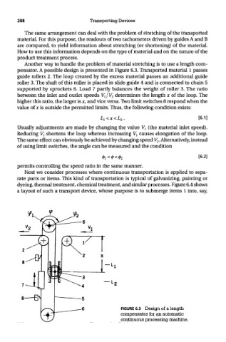
Another way to handle the problem of material stretching is to use a length com-
pensator. A possible design is presented in Figure 6.3. Transported material 1 passes
guide rollers 2. The loop created by the excess material passes an additional guide
roller 3. The shaft of this roller is placed in slide guide 4 and is connected to chain 5
supported by sprockets 6. Load 7 partly balances the weight of roller 3. The ratio
between the inlet and outlet speeds V l/V 2 determines the length x of the loop. The
higher this ratio, the larger is x, and vice versa. Two limit switches 8 respond when the
value of x is outside the permitted limits. Thus, the following condition exists:
Usually adjustments are made by changing the value V l (the material inlet speed).
Reducing V^ shortens the loop whereas increasing V l causes elongation of the loop.
The same effect can obviously be achieved by changing speed V 2. Alternatively, instead
of using limit switches, the angle can be measured and the condition
permits controlling the speed ratio in the same manner.
Next we consider processes where continuous transportation is applied to sepa-
rate parts or items. This kind of transportation is typical of galvanizing, painting or
dyeing, thermal treatment, chemical treatment, and similar processes. Figure 6.4 shows
a layout of such a transport device, whose purpose is to submerge items 1 into, say,
FIGURE 6.3 Design of a length
compensator for an automatic
continuous processing machine.