
Page 250 - Robots Androids and Animatrons : 12 Incredible Projects You Can Build
P. 250
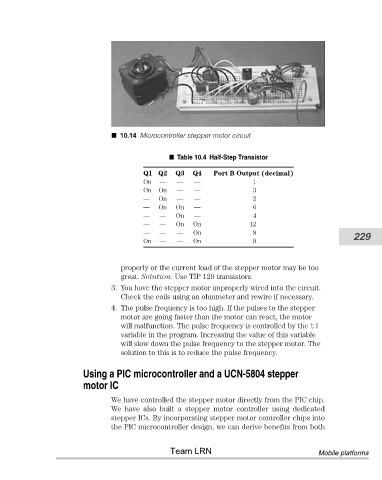
10.14 Microcontroller stepper motor circuit


                                                         Table 10.4 Half-Step Transistor
                                                Q1 Q2    Q3   Q4   Port B Output (decimal)
                                                On  —    —    —               1
                                                On  On   —    —               3
                                                —   On   —    —               2
                                                —   On   On   —               6
                                                —   —    On   —               4
                                                —   —    On   On             12
                                                —   —    —    On              8                           229
                                                On  —    —    On              9


                                          properly or the current load of the stepper motor may be too
                                          great. Solution: Use TIP 120 transistors.
                                       3. You have the stepper motor improperly wired into the circuit.
                                          Check the coils using an ohmmeter and rewire if necessary.
                                       4. The pulse frequency is too high. If the pulses to the stepper
                                          motor are going faster than the motor can react, the motor
                                          will malfunction. The pulse frequency is controlled by the ti
                                          variable in the program. Increasing the value of this variable
                                          will slow down the pulse frequency to the stepper motor. The
                                          solution to this is to reduce the pulse frequency.


                               Using a PIC microcontroller and a UCN-5804 stepper
                               motor IC

                                       We have controlled the stepper motor directly from the PIC chip.
                                       We  have  also  built  a  stepper  motor  controller  using  dedicated
                                       stepper ICs. By incorporating stepper motor controller chips into
                                       the PIC microcontroller design, we can derive benefits from both


                                                       Team LRN                                  Mobile platforms