
Page 251 - Robots Androids and Animatrons : 12 Incredible Projects You Can Build
P. 251
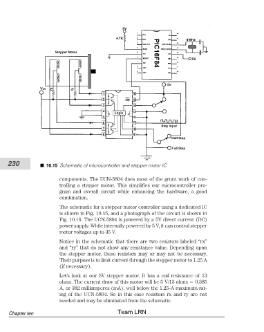
230            10.15 Schematic of microcontroller and stepper motor IC


                                components. The UCN-5804 does most of the grunt work of con-
                                trolling  a  stepper  motor.  This  simplifies  our  microcontroller  pro-
                                gram  and  overall  circuit  while  enhancing  the  hardware,  a  good
                                combination.
                                The schematic for a stepper motor controller using a dedicated IC
                                is shown in Fig. 10.15, and a photograph of the circuit is shown in
                                Fig. 10.16. The UCN-5804 is powered by a 5V direct current (DC)
                                power supply. While internally powered by 5 V, it can control stepper
                                motor voltages up to 35 V.

                                Notice in the schematic that there are two resistors labeled “rx”
                                and “ry” that do not show any resistance value. Depending upon
                                the  stepper  motor,  these  resistors  may  or  may  not  be  necessary.
                                Their purpose is to limit current through the stepper motor to 1.25 A
                                (if necessary).
                                Let’s look at our 5V stepper motor. It has a coil resistance of 13
                                ohms. The current draw of this motor will be 5 V/13 ohms   0.385
                                A, or 382 milliamperes (mA), well below the 1.25-A maximum rat-
                                ing of the UCN-5804. So in this case resistors rx and ry are not
                                needed and may be eliminated from the schematic.
                                                       Team LRN
            Chapter ten