
Page 246 - Robots Androids and Animatrons : 12 Incredible Projects You Can Build
P. 246
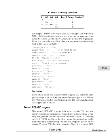
Port B Output (decimal)
                                                Q1 Q2
                                                         Q3
                                                             Q4
                                                                              1
                                                         —
                                                              —
                                                On  —    Table 10.3 Full-Step Transistors
                                                —   On   —    —               2
                                                —   —    On   —               4
                                                —   —    —   On               8
                                       and simple to show how easy it is to get a stepper motor moving.
                                       Table 10.3 shows that each step in the sequence turns on one tran-
                                       sistor. Use Table 10.3 to follow the logic in the PICBASIC program.
                                       When you reach the end of the table, the sequence repeats starting
                                       back at the top of the table.
                                       ‘Stepper Motor Controller
                                       Symbol TRISB = 134  ‘Initialize TRISB to 134
                                       Symbol PortB = 6  ‘Initialize portb to 6
                                       symbol ti = b6  ‘Initial ti delay
                                       ti = 25   ‘Set delay to 25 ms
                                       Poke TRISB,0  ‘Set PORTB lines output
                                       start:   ‘Forward rotation sequence
                                       poke portb,1  ‘Step 1
                                       pause ti  ‘Delay                                                   225
                                       poke portb,2  ‘Step 2
                                       pause ti  ‘Delay
                                       poke portb,4  ‘Step 3
                                       pause ti  ‘Delay
                                       poke portb,8  ‘Step 4
                                       pause ti  ‘Delay
                                       goto start  ‘Do again
                                       One rotation

                                       Using whole steps, the stepper motor requires 200 pulses to com-
                                       plete a single rotation (360 degrees/1.8 degrees per step). Having
                                       the PIC microcontroller count pulses allows it to control and position
                                       the stepper motor’s rotor.

                               Second PICBASIC program

                                       This second PICBASIC program is far more versatile. The user can
                                       modify programmed parameters (time delay) as the program is run-
                                       ning using one of the four switches connected to port A. Pressing
                                       switch 1 (SW1) lengthens the delay pause between steps in the
                                       sequence  and  subsequently  makes  the  stepper  motor  rotate
                                       slower. Pressing SW2 has the opposite effect. If you press SW3,

                                                       Team LRN                                  Mobile platforms