
Page 243 - Robots Androids and Animatrons : 12 Incredible Projects You Can Build
P. 243
brought high, the chip operates in the half-step mode. This mode
doubles the resolution of the stepper motor. For instance, the motor
we are using rotates the shaft 1.8 degrees per step. When operating
in the half-step mode, the shaft rotates 0.9 degrees per step and the
overall rotation speed [revolutions per minute (rpm)] of the shaft
will be one-half of the speed of the full-step mode. If pin 10 is
brought to ground, the UCN-5804 will operate in full-step mode.
Connecting a wheel to a stepper motor shaft
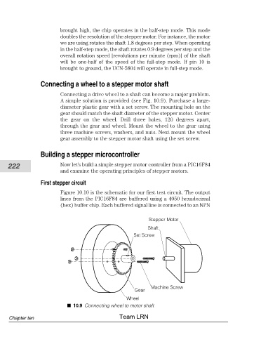
Connecting a drive wheel to a shaft can become a major problem.
A simple solution is provided (see Fig. 10.9). Purchase a large-
diameter plastic gear with a set screw. The mounting hole on the
gear should match the shaft diameter of the stepper motor. Center
the gear on the wheel. Drill three holes, 120 degrees apart,
through the gear and wheel. Mount the wheel to the gear using
three machine screws, washers, and nuts. Next mount the wheel
gear assembly to the stepper motor shaft using the set screw.
Building a stepper microcontroller
222 Now let’s build a simple stepper motor controller from a PIC16F84
and examine the operating principles of stepper motors.
First stepper circuit
Figure 10.10 is the schematic for our first test circuit. The output
lines from the PIC16F84 are buffered using a 4050 hexadecimal
(hex) buffer chip. Each buffered signal line is connected to an NPN
Stepper Motor
Shaft
Set Screw
Machine Screw
Gear
Wheel
10.9 Connecting wheel to motor shaft
Team LRN
Chapter ten