Page 241 - Robots Androids and Animatrons : 12 Incredible Projects You Can Build
P. 241

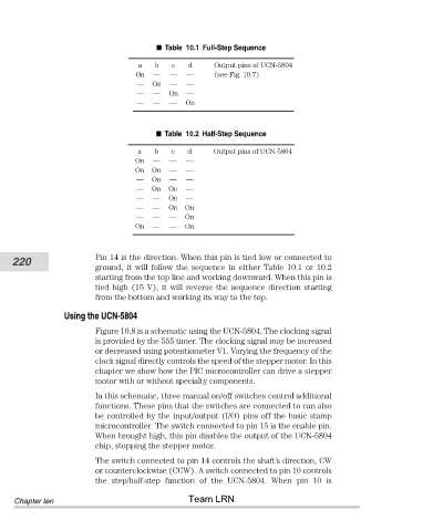
Table  10.1 Full-Step Sequence
                                               b
                                                       d
                                           a
                                                   c
                                          On   —   —   —      Output pins of UCN-5804
                                                              (see Fig. 10.7)
                                          —   On   —   —
                                          —    —   On  —
                                          —    —   —   On
                                                 Table  10.2 Half-Step Sequence
                                           a   b   c   d      Output pins of UCN-5804
                                          On  —    —   —
                                          On  On   —   —
                                          —   On   —   —
                                          —   On  On   —
                                          —   —   On   —
                                          —   —   On   On
                                          —   —    —   On
                                          On  —    —   On


                                Pin 14 is the direction. When this pin is tied low or connected to
           220
                                ground,  it  will  follow  the  sequence  in  either  Table  10.1  or  10.2
                                starting from the top line and working downward. When this pin is
                                tied high (15 V), it will reverse the sequence direction starting
                                from the bottom and working its way to the top.

                        Using the UCN-5804
                                Figure 10.8 is a schematic using the UCN-5804. The clocking signal
                                is provided by the 555 timer. The clocking signal may be increased
                                or decreased using potentiometer V1. Varying the frequency of the
                                clock signal directly controls the speed of the stepper motor. In this
                                chapter we show how the PIC microcontroller can drive a stepper
                                motor with or without specialty components.
                                In this schematic, three manual on/off switches control additional
                                functions. These pins that the switches are connected to can also
                                be controlled by the input/output (I/O) pins off the basic stamp
                                microcontroller. The switch connected to pin 15 is the enable pin.
                                When brought high, this pin disables the output of the UCN-5804
                                chip, stopping the stepper motor.
                                The switch connected to pin 14 controls the shaft’s direction, CW
                                or counterclockwise (CCW). A switch connected to pin 10 controls
                                the  step/half-step  function  of  the  UCN-5804.  When  pin  10  is
                                                       Team LRN
            Chapter ten
   236   237   238   239   240   241   242   243   244   245   246