
Page 239 - Robots Androids and Animatrons : 12 Incredible Projects You Can Build
P. 239
Determine Wire Setup
218 Read Resistance Values to
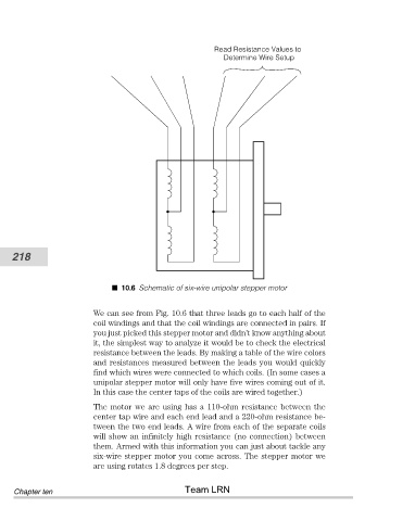
10.6 Schematic of six-wire unipolar stepper motor
We can see from Fig. 10.6 that three leads go to each half of the
coil windings and that the coil windings are connected in pairs. If
you just picked this stepper motor and didn’t know anything about
it, the simplest way to analyze it would be to check the electrical
resistance between the leads. By making a table of the wire colors
and resistances measured between the leads you would quickly
find which wires were connected to which coils. (In some cases a
unipolar stepper motor will only have five wires coming out of it.
In this case the center taps of the coils are wired together.)
The motor we are using has a 110-ohm resistance between the
center tap wire and each end lead and a 220-ohm resistance be-
tween the two end leads. A wire from each of the separate coils
will show an infinitely high resistance (no connection) between
them. Armed with this information you can just about tackle any
six-wire stepper motor you come across. The stepper motor we
are using rotates 1.8 degrees per step.
Team LRN
Chapter ten