
Page 244 - Robots Androids and Animatrons : 12 Incredible Projects You Can Build
P. 244
223
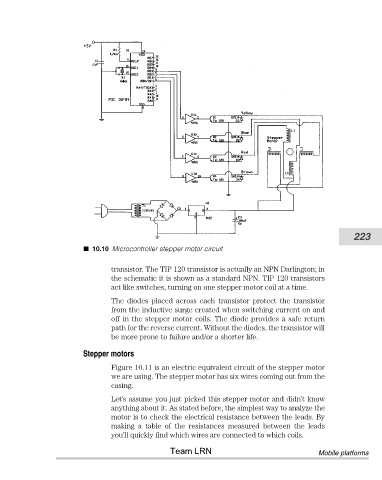
10.10 Microcontroller stepper motor circuit
transistor. The TIP 120 transistor is actually an NPN Darlington; in
the schematic it is shown as a standard NPN. TIP 120 transistors
act like switches, turning on one stepper motor coil at a time.
The diodes placed across each transistor protect the transistor
from the inductive surge created when switching current on and
off in the stepper motor coils. The diode provides a safe return
path for the reverse current. Without the diodes, the transistor will
be more prone to failure and/or a shorter life.
Stepper motors
Figure 10.11 is an electric equivalent circuit of the stepper motor
we are using. The stepper motor has six wires coming out from the
casing.
Let’s assume you just picked this stepper motor and didn’t know
anything about it. As stated before, the simplest way to analyze the
motor is to check the electrical resistance between the leads. By
making a table of the resistances measured between the leads
you’ll quickly find which wires are connected to which coils.
Team LRN Mobile platforms