
Page 240 - Robots Androids and Animatrons : 12 Incredible Projects You Can Build
P. 240
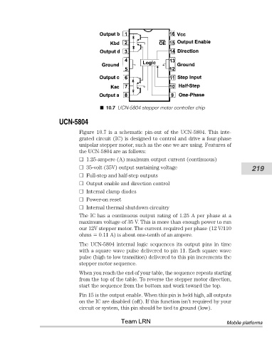
10.7 UCN-5804 stepper motor controller chip


                               UCN-5804
                                       Figure  10.7  is  a  schematic  pin-out  of  the  UCN-5804.  This  inte-
                                       grated circuit (IC) is designed to control and drive a four-phase
                                       unipolar stepper motor, such as the one we are using. Features of
                                       the UCN-5804 are as follows:
                                         1.25-ampere (A) maximum output current (continuous)
                                         35-volt (35V) output sustaining voltage                          219
                                         Full-step and half-step outputs
                                         Output enable and direction control
                                         Internal clamp diodes
                                         Power-on reset
                                         Internal thermal shutdown circuitry
                                       The IC has a continuous output rating of 1.25 A per phase at a
                                       maximum voltage of 35 V. This is more than enough power to run
                                       our 12V stepper motor. The current required per phase (12 V/110
                                       ohms   0.11 A) is about one-tenth of an ampere.
                                       The  UCN-5804  internal  logic  sequences  its  output  pins  in  time
                                       with a square wave pulse delivered to pin 11. Each square wave
                                       pulse (high to low transition) delivered to this pin increments the
                                       stepper motor sequence.

                                       When you reach the end of your table, the sequence repeats starting
                                       from the top of the table. To reverse the stepper motor direction,
                                       start the sequence from the bottom and work toward the top.
                                       Pin 15 is the output enable. When this pin is held high, all outputs
                                       on the IC are disabled (off). If this function isn’t required by your
                                       circuit or system, this pin should be tied to ground (low).

                                                       Team LRN                                  Mobile platforms