
Page 252 - Robots Androids and Animatrons : 12 Incredible Projects You Can Build
P. 252
Before we move on, let’s look at one more case. A 12V stepper motor
has a phase (coil) resistance of 6 ohms. The current drawn by this
motor is 12 V/6 ohms 2 A. This is above the UCN-5804 maximum
current rating. To use this stepper motor, you must add the rx and ry
resistors. The rx and ry resistor values should be equal to each other,
so each phase will have the same torque. The values chosen for these
resistors should limit the current drawn to 1.25 A or less. In this case
the resistors should be at least 4 ohms [5 to 10 watts (W)]. With the
resistors in place the current drawn is 12 V/10 ohms 1.20 A.
The inputs to the UCN-5804 are compatible with complementary
metal-oxide semiconductor (CMOS) and transistor-transistor logic
(TTL). This means we can connect the outputs from our PIC mi-
crocontroller directly to the UCN-5804 and expect it to function
properly. The step input (pin 11) to the UCN-5804 is generated by
the PIC microcontroller. The output enable pin when held low en-
ables the stepper motor; when brought high, it disables (stops)
the stepper motor.
Pins 10 and 14 on the UCN-5804 are controlled by switches that
bring the pins to a logic high or low. Pin 10 controls whether the
output to the stepper motor will be full-step or half-step, and pin
14 controls direction. If we want, these options may also be put 231
under the PIC control. The pins are brought to a logic high or low
to activate the options just like the output enable pin.
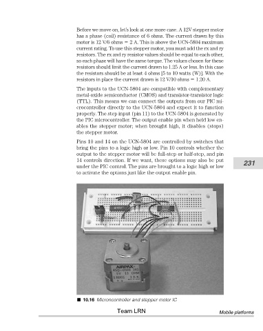
10.16 Microncontroller and stepper motor IC
Team LRN Mobile platforms