
Page 55 - Robots Androids and Animatrons : 12 Incredible Projects You Can Build
P. 55
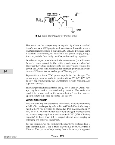
3.8 Basic power supply for charger circuit


                                The power for the charger may be supplied by either a standard
                                transformer or a VDC plug-in wall transformer. I would choose a
                                wall transformer because it supplies a DC voltage. If you are using
                                a standard transformer, you must build the power supply, using a
                                line cord, switch, fuse, bridge rectifier, and smoothing capacitor.
                                In either case you should match the transformer (or wall trans-
                                former)  power  output  to  the  battery  pack  you  are  charging.
                                Matching the voltage and current to the battery pack reduces the
                                power the LM317 must dissipate; for example, you wouldn’t want
           34                   to use a 12V transformer to charge a 6V battery pack.

                                Figure  3.8  is  a  basic  VDC  power  supply  for  the  charger.  The
                                power supply can be made to provide either 6V, 12V, 18V, 24V,
                                or 36V depending upon the transformer, bridge rectifier, and
                                capacitor chosen.

                                The charger circuit is illustrated in Fig. 3.9. It uses an LM317 volt-
                                age  regulator  and  a  current-limiting  resistor.  The  resistance
                                needed to be provided by the current-limiting resistor depends
                                upon the current needed to charge the battery.

                                Current-limiting resistor
                                Most NiCd battery manufacturers recommend charging the battery
                                at 1/10 of its rated capacity, referred to as C/10. So if an AA battery is
                                rated at 0.850 Ah, it should be charged at 1/10 that capacity, or 85
                                mA, for 14 h. After the batteries are fully charged, manufacturers
                                recommend dropping the current to around C/30 (1/30 of battery
                                capacity)  to  keep  them  fully  charged  without  overcharging  or
                                damaging the batteries in any way.
                                For our example, we will configure the charger to recharge four C
                                cells in series. Each C cell is rated at 2000 mA. So our C/10 rate is
                                200 mA. The typical voltage rating from this battery is approxi-


                                                       Team LRN
            Chapter three