
Page 56 - Robots Androids and Animatrons : 12 Incredible Projects You Can Build
P. 56
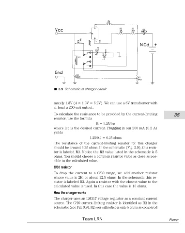
3.9 Schematic of charger circuit


                                       mately 1.3V (4   1.3V   5.2V). We can use a 6V transformer with
                                       at least a 200-mA output.
                                       To calculate the resistance to be provided by the current-limiting   35
                                       resistor, use the formula
                                                               R   1.25/Icc
                                       where Icc is the desired current. Plugging in our 200 mA (0.2 A)
                                       yields
                                                            1.25/0.2   6.25 ohms
                                       The  resistance  of  the  current-limiting  resistor  for  this  charger
                                       should be around 6.25 ohms. In the schematic (Fig. 3.9), this resis-
                                       tor is labeled R2. Notice the R2 value listed in the schematic is 5
                                       ohms. You should choose a common resistor value as close as pos-
                                       sible to the calculated value.
                                       C/30 resistor
                                       To  drop  the  current  to  a  C/30  range,  we  add  another  resistor
                                       whose value is 2R, or about 12.5 ohms. In the schematic this re-
                                       sistor is labeled R3. Again a resistor with the closest value to the
                                       calculated value is used. In this case the value is 10 ohms.
                                       How the charger works
                                       The charger uses an LM317 voltage regulator as a constant current
                                       source. The C/10 current-limiting resistor is identified as R2 in the
                                       schematic (see Fig. 3.9). R2 you will notice is only 5 ohms as compared


                                                       Team LRN                                          Power