Page 72 - Robots Androids and Animatrons : 12 Incredible Projects You Can Build
P. 72

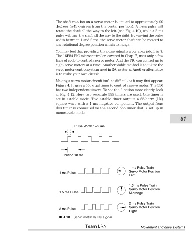
The shaft rotation on a servo motor is limited to approximately 90
                                       degrees (±45 degrees from the center position). A 1-ms pulse will
                                       rotate the shaft all the way to the left (see Fig. 4.10), while a 2-ms
                                       pulse will turn the shaft all the way to the right. By varying the pulse
                                       width between 1 and 2 ms, the servo motor shaft can be rotated to
                                       any rotational degree position within its range.
                                       You may feel that providing the pulse signal is a complex job; it isn’t.
                                       The 16F84 PIC microcontroller, covered in Chap. 7, uses only a few
                                       lines of code to control a servo motor. And the PIC can control up to
                                       eight servo motors at a time. Another viable method is to utilize the
                                       servo motor control system used in R/C systems. Another alternative
                                       is to make your own circuit.
                                       Making a servo motor circuit isn’t as difficult as it may first appear.
                                       Figure 4.11 uses a 556 dual timer to control a servo motor. The 556
                                       has two independent timers. To see the function more clearly, look
                                       at Fig. 4.12. Here two separate 555 timers are used. One timer is
                                       set in astable mode. The astable timer outputs a 55-hertz (Hz)
                                       square wave with a 1-ms negative component. The output from
                                       this timer is connected to the second 555 timer that is set up in
                                       monostable mode.
                                                                                                            51

                                                 Pulse Width 1–2 ms


                                           Period 18 ms


                                                                               1 ms Pulse Train
                                                                               Servo Motor Position
                                         1 ms Pulse
                                                                               Left
                                                                               1.5 ms Pulse Train
                                                                               Servo Motor Position
                                         1.5 ms Pulse                          Midrange


                                                                               2 ms Pulse Train
                                                                               Servo Motor Position
                                         2 ms Pulse
                                                                               Right
                                           4.10 Servo motor pulse signal

                                                       Team LRN                       Movement and drive systems
   67   68   69   70   71   72   73   74   75   76   77