
Page 76 - Robots Androids and Animatrons : 12 Incredible Projects You Can Build
P. 76
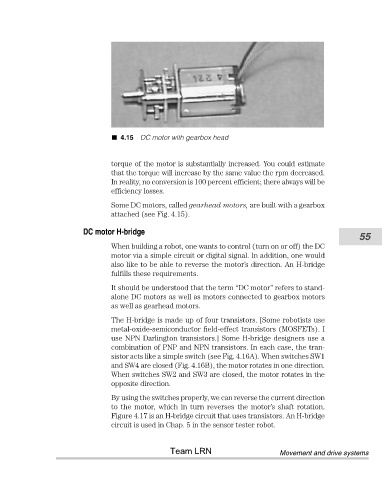
4.15 DC motor with gearbox head


                                       torque of the motor is substantially increased. You could estimate
                                       that the torque will increase by the same value the rpm decreased.
                                       In reality, no conversion is 100 percent efficient; there always will be
                                       efficiency losses.

                                       Some DC motors, called gearhead motors, are built with a gearbox
                                       attached (see Fig. 4.15).

                               DC motor H-bridge
                                                                                                            55
                                       When building a robot, one wants to control (turn on or off) the DC
                                       motor via a simple circuit or digital signal. In addition, one would
                                       also like to be able to reverse the motor’s direction. An H-bridge
                                       fulfills these requirements.
                                       It should be understood that the term “DC motor” refers to stand-
                                       alone DC motors as well as motors connected to gearbox motors
                                       as well as gearhead motors.

                                       The H-bridge is made up of four transistors. [Some robotists use
                                       metal-oxide-semiconductor field-effect transistors (MOSFETs). I
                                       use NPN Darlington transistors.] Some H-bridge designers use a
                                       combination of PNP and NPN transistors. In each case, the tran-
                                       sistor acts like a simple switch (see Fig. 4.16A). When switches SW1
                                       and SW4 are closed (Fig. 4.16B), the motor rotates in one direction.
                                       When switches SW2 and SW3 are closed, the motor rotates in the
                                       opposite direction.
                                       By using the switches properly, we can reverse the current direction
                                       to the motor, which in turn reverses the motor’s shaft rotation.
                                       Figure 4.17 is an H-bridge circuit that uses transistors. An H-bridge
                                       circuit is used in Chap. 5 in the sensor tester robot.


                                                       Team LRN                       Movement and drive systems