
Page 73 - Robots Androids and Animatrons : 12 Incredible Projects You Can Build
P. 73
10K
F
10K
R2 R1 Vcc .01 Vcc
R3
2.2K
1 3 14
10
.1 F C1 2 4
13
6 R4
150
9
12
7 5 10 F
C2
+
Vcc Servo
Motor
M
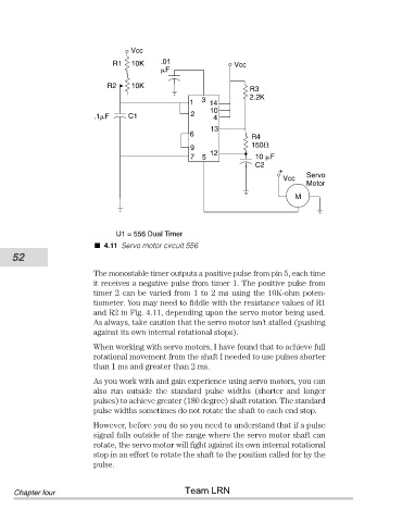
U1 = 556 Dual Timer
4.11 Servo motor circuit 556
52
The monostable timer outputs a positive pulse from pin 5, each time
it receives a negative pulse from timer 1. The positive pulse from
timer 2 can be varied from 1 to 2 ms using the 10K-ohm poten-
tiometer. You may need to fiddle with the resistance values of R1
and R2 in Fig. 4.11, depending upon the servo motor being used.
As always, take caution that the servo motor isn’t stalled (pushing
against its own internal rotational stops).
When working with servo motors, I have found that to achieve full
rotational movement from the shaft I needed to use pulses shorter
than 1 ms and greater than 2 ms.
As you work with and gain experience using servo motors, you can
also run outside the standard pulse widths (shorter and longer
pulses) to achieve greater (180 degree) shaft rotation. The standard
pulse widths sometimes do not rotate the shaft to each end stop.
However, before you do so you need to understand that if a pulse
signal falls outside of the range where the servo motor shaft can
rotate, the servo motor will fight against its own internal rotational
stop in an effort to rotate the shaft to the position called for by the
pulse.
Team LRN
Chapter four