
Page 147 - Rock Mechanics For Underground Mining
P. 147
SHEAR BEHAVIOUR OF DISCONTINUITIES
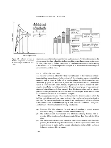
Figure 4.46 Influence of scale on decreases, and so the nett apparent friction angle decreases. As the scale increases, the
the three components of discontinu- steeper asperities shear off and the inclination of the controlling roughness decreases.
ity shear strength (after Bandis et al., Similarly, the asperity failure component of roughness decreases with increasing
1981).
scale because the material compressive strength, JCS, decreases with increasing size
as discussed in section 4.3.5.
4.7.5 Infilled discontinuities
The previous discussion referred to ‘clean’ discontinuities or discontinuities contain-
ing no infilling materials. As noted in section 3.3, discontinuities may contain infilling
materials such as gouge in faults, silt in bedding planes, low-friction materials such
as chlorite, graphite and serpentine in joints, and stronger materials such as quartz or
calcite in veins or healed joints. Clearly, the presence of these materials will influ-
ence the shear behaviour of discontinuities. The presence of gouge or clay seams can
decrease both stiffness and shear strength. Low-friction materials such as chlorite,
graphite and serpentine can markedly decrease friction angles, while vein materials
such as quartz can serve to increase shear strengths.
Of particular concern is the behaviour of major infilled discontinuities in which the
infilling materials are soft and weak, having similar mechanical properties to clays
and silts. The shear strengths of these materials are usually described by an effective
stress Coulomb law. In a laboratory study of such filled discontinuities, Ladanyi and
Archambault (1977) reached the following conclusions:
(a) For most filled discontinuities, the peak strength envelope is located between
that for the filling and that for a similar clean discontinuity.
(b) The stiffnesses and shear strength of a filled discontinuity decrease with in-
creasing filling thickness, but always remain higher than those of the filling
alone.
(c) The shear stress–displacement curves of filled discontinuities often have two
portions, the first reflecting the deformability of the filling materials before rock
to rock contact is made, and the second reflecting the deformability and shear
failure of rock asperities in contact.
129