
Page 267 - Rock Mechanics For Underground Mining
P. 267
IDENTIFICATION OF POTENTIAL BLOCK FAILURE MODES – BLOCK THEORY
removability can be applied to identify potentially unstable blocks. Consider a rock
◦
mass with joint sets oriented 30 /90 ,60 /45 and 20 /330 and an excavation with
◦
◦
◦
◦
◦
a horizontal roof. The construction showing the formation of the spherical triangles
of the JPs is shown in Figure 9.8(a). From the diagram it is clear that, of the eight
JPs, only JP 101 has no intersection with the EP. This is shown more clearly in
Figure 9.8(b), where all JPs except JP 101 have been removed. This means that the
only blocks removable from the excavation roof are those formed by the intersection
of the lower surface of joint set 1, the upper surface of joint set 2, the lower surface
of joint set 3 and the horizontal surface of the excavation roof.
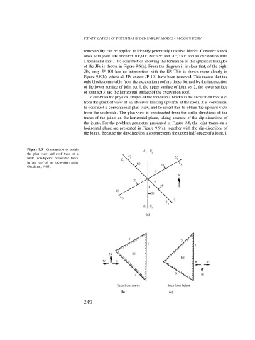
To establish the physical shapes of the removable blocks in the excavation roof (i.e.
from the point of view of an observer looking upwards at the roof), it is convenient
to construct a conventional plan view, and to invert this to obtain the upward view
from the underside. The plan view is constructed from the strike directions of the
traces of the joints on the horizontal plane, taking account of the dip directions of
the joints. For the problem geometry presented in Figure 9.8, the joint traces on a
horizontal plane are presented in Figure 9.9(a), together with the dip directions of
the joints. Because the dip direction also represents the upper half-space of a joint, it
Figure 9.9 Construction to obtain
the plan view and roof trace of a
finite, non-tapered removable block
in the roof of an excavation (after
Goodman, 1989).
249