
Page 268 - Rock Mechanics For Underground Mining
P. 268
EXCAVATION DESIGN IN BLOCKY ROCK
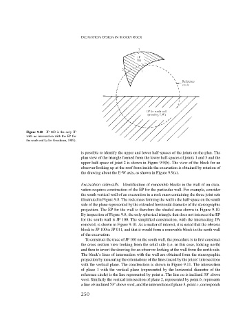
Figure 9.10 JP 100 is the only JP
with no intersection with the EP for
the south wall (after Goodman, 1989).
is possible to identify the upper and lower half-spaces of the joints on the plan. The
plan view of the triangle formed from the lower half-spaces of joints 1 and 3 and the
upper half-space of joint 2 is shown in Figure 9.9(b). The view of the block for an
observer looking up at the roof from inside the excavation is obtained by rotation of
the drawing about the E-W axis, as shown in Figure 9.9(c).
Excavation sidewalls. Identification of removable blocks in the wall of an exca-
vation requires construction of the EP for the particular wall. For example, consider
the south vertical wall of an excavation in a rock mass containing the three joint sets
illustrated in Figure 9.8. The rock mass forming the wall is the half-space on the south
side of the plane represented by the extended horizontal diameter of the stereographic
projection. The EP for the wall is therefore the shaded area shown in Figure 9.10.
By inspection of Figure 9.8, the only spherical triangle that does not intersect the EP
for the south wall is JP 100. The simplified construction, with the intersecting JPs
removed, is shown in Figure 9.10. As a matter of interest, it is noted that the obverse
block to JP 100 is JP 011, and that it would form a removable block in the north wall
of the excavation.
To construct the trace of JP 100 on the south wall, the procedure is to first construct
the cross section view looking from the solid side (i.e. in this case, looking north)
and then to invert the drawing for an observer looking at the wall from the north side.
The block’s lines of intersection with the wall are obtained from the stereographic
projection by measuring the orientations of the lines traced by the joints’ intersections
with the vertical plane. The construction is shown in Figure 9.11. The intersection
of plane 1 with the vertical plane (represented by the horizontal diameter of the
◦
reference circle) is the line represented by point a. The line oa is inclined 30 above
west. Similarly the vertical intersection of plane 2, represented by point b, represents
◦
a line ob inclined 53 above west, and the intersection of plane 3, point c, corresponds
250