
Page 270 - Rock Mechanics For Underground Mining
P. 270
EXCAVATION DESIGN IN BLOCKY ROCK
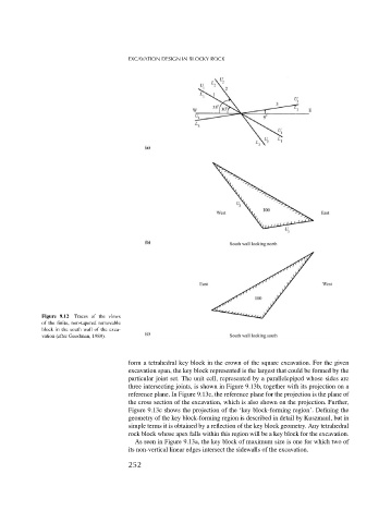
Figure 9.12 Traces of the views
of the finite, non-tapered removable
block in the south wall of the exca-
vation (after Goodman, 1989).
form a tetrahedral key block in the crown of the square excavation. For the given
excavation span, the key block represented is the largest that could be formed by the
particular joint set. The unit cell, represented by a parallelepiped whose sides are
three intersecting joints, is shown in Figure 9.13b, together with its projection on a
reference plane. In Figure 9.13c, the reference plane for the projection is the plane of
the cross section of the excavation, which is also shown on the projection. Further,
Figure 9.13c shows the projection of the ‘key block-forming region’. Defining the
geometry of the key block-forming region is described in detail by Kuszmaul, but in
simple terms it is obtained by a reflection of the key block geometry. Any tetrahedral
rock block whose apex falls within this region will be a key block for the excavation.
As seen in Figure 9.13a, the key block of maximum size is one for which two of
its non-vertical linear edges intersect the sidewalls of the excavation.
252