
Page 275 - Rock Mechanics For Underground Mining
P. 275
SYMMETRIC TRIANGULAR ROOF PRISM
The following analysis is intended to establish the key factors affecting the stability
of a symmetric roof prism, for the case < . It is an example of a relaxation
method of analysis, proposed originally by Bray (1977). The procedure takes explicit
account of the deformation properties of the joints defining the crown prism. Initially,
the joint normal and shear stiffnesses K n and K s are assumed to be sufficiently high
for the presence of the joints to be ignored. It is then possible to determine the stress
distribution around the opening assuming the rock behaves as an elastic continuum.
Since no body forces are induced in the medium by the process of excavating the
opening, the elastic analysis takes account implicitly of the weight of the medium.
Such an analysis allows the state of stress to be calculated at points in the rock mass
coinciding with the surfaces of the prism. It is then a simple matter to estimate the
magnitudes of the surface forces acting on the prism from the magnitudes of the stress
components and the area and orientation of each surface.
The relaxation method proceeds by introducing the joint stiffnesses K n and K s ,
and examining the displacements subsequently experienced by the block caused by
joint deformation. Since real joint stiffnesses are low compared with the elasticity of
the rock material, the deformability of the prism can be neglected in this process. As
defined previously, the block is subject to its own weight, W, and some support force,
R, whose resultant is P = W − R, as well as the joint surface forces. The analysis
proceeds through the displacements of the body under the influence of the internal
surface forces and the vertical force producing limiting equilibrium, P , defined by
equation 9.19. The state of stability of the prism is then assessed through the factor
of safety against roof failure, defined by
P
FofS = (9.20)
P
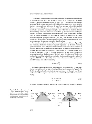
Before the relaxation process (i.e. before applying the limiting force P and reduc-
ing the joint stiffnesses), the state of loading of the prism is as shown in Figure 9.15a.
In this case, the surface forces N 0 , S 0 account completely for the static equilibrium
of the prism. These original surface forces are related to the internal horizontal force
H 0 by
N 0 = H 0 cos
(9.21)
S 0 = H 0 sin
When the resultant force P is applied, the wedge is displaced vertically through a
Figure 9.15 Free-body diagrams of
a crown prism (a) subject to sur-
face forces corresponding to elastic
stresses, and (b) in a state of limiting
equilibrium after external load appli-
cation and joint relaxation.
257