
Page 280 - Rock Mechanics For Underground Mining
P. 280
EXCAVATION DESIGN IN BLOCKY ROCK
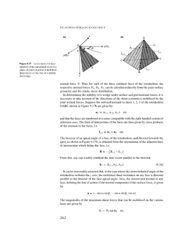
Figure 9.17 (a) Geometry for deter-
mination of the unit normal vector to a
plane; (b) lines of action of mobilised
shear forces on the face of a tetrahe-
dral wedge.
normal force N. Thus for each of the three confined faces of the tetrahedron, the
respective normal forces N 1 , N 2 , N 3 , can be calculated directly from the joint surface
geometry and the elastic stress distribution.
In determining the stability of a wedge under surface and gravitational forces, it is
necessary to take account of the directions of the shear resistances mobilised by the
joint normal forces. Suppose the outward normals to faces 1, 2, 3 of the tetrahedron
OABC shown in Figure 9.17b are given by
n 1 = (n x1 , n y1 , n z1 ) etc.
and that the faces are numbered in a sense compatible with the right-handed system of
reference axes. The lines of intersection of the faces are then given by cross products
of the normals to the faces, i.e.
l 1,2 = n 1 × n 2 etc.
The bisector of an apical angle of a face of the tetrahedron, and directed towards the
apex, as shown in Figure 9.17b, is obtained from the orientations of the adjacent lines
of intersection which define the face, i.e.
1
B =− (l 1,2 + l 3,1 )
2
From this, one can readily establish the unit vector parallel to the bisector,
b 1 = (b x1 , b y1 , b z1 ) (9.34)
It can be reasonably assumed that, in the case where the crown trihedral angle of the
tetrahedron includes the z axis, the mobilised shear resistance on any face is directed
parallel to the bisector of the face apical angle. Also, the inward unit normal to any
face, defining the line of action of the normal component of the surface force, is given
by
a = (− sin cos , − sin sin , cos )
The magnitudes of the maximum shear forces that can be mobilised on the various
faces are given by
S 1 = N 1 tan 1 etc.
262